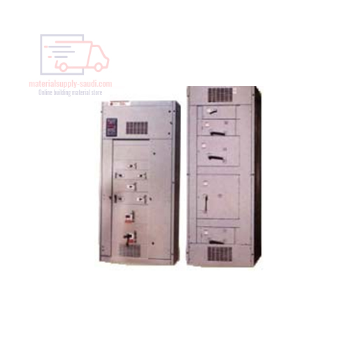
- Pow-R-Line 4B panel board utilizes circuit breakers. Pow-R-Line 4F Panelboards utilizes types FDPW fusible switches.
- A single chassis accommodates both circuit breakers and fusible switches.
- Main and neutral are located at the same ends to provide additional space for branch devices.
- Three-piece trim facilities installations.
- Will accommodate Series C Circuit Breakers to provide higher ratings in a standard chassis and increased series ratings.
- UL tested and listed. Meets NEC and NEMA tandards.
General Construction Features
WESCOSA assembled Panelboards as per Cutler-Hammer technologies are designed for sequence phase connection of branch circuit devices. This allows complete flexibility of circuit arrangement (1-, 2- or 3-poles) to allow balance of the electrical load on each phase.Sturdy rigid chassis assembly assures accurate alignment of interior with panel front; prevents flexing and minimizes possibility of loosening or damage to current carrying parts during and after installation.Four-point in-and-out adjustment of panel interior is provided to meet critical depth dimension on flush installations. This compensates for possible alignment of box at installation. Main lungs are mechanical solder less type and approved for copper of aluminum conductors.
TECHNICAL DATA
Table 1: Panelboards Selection Guide
|
Panelboard Type |
Device Type |
Maximum Voltage Rating |
Maximum Main Rating, Amperes |
Branch Circuit Ampere Range |
Short Circuit Current
Ratings rms Symmetrical Amperes, AC |
|||
|
AC |
DC |
Main Lugs Only |
Main Device |
Fully Rated (kA) |
Series Rated (kA) |
|||
| Pow-R-Line 1a | Breaker | 240 | – | 600 | 600 | 15 – 100 | 10 – 22 | 22 – 200 |
| Pow-R-Line 2a | Breaker | 240
480Y/227 |
250 | 600
600 |
600
600 |
15 – 100
15 – 100 |
65
14 |
65 – 200
22 – 150 |
| Pow-R-Line 3a | Breaker | 240
480 600 |
250 | 800
800 800 |
600
600 600 |
15 – 225
15 – 225 15 – 225 |
10 – 200
14 – 100 14 – 35 |
22 – 200
22 – 150 – |
| Pow-R-Line 4b | Breaker | 240
480 600 |
250 | 1200
1200 1200 |
1200
1200 1200 |
15 – 1200
15 – 1200 15 – 1200 |
10 – 200
14 – 200 14 – 200 |
22 – 200
22 – 150 – |
| Pow-R-Line 4f | Fusible Switch | 240
600 |
250 | 1200
1200 |
1200
1200 |
30 – 1200
30 – 1200 |
100 – 200
100 – 200 |
–
– |
Table 2: Standard Main Lug Terminals
|
Panel Type |
Wire Size Ranges for Ampere Capacity | ||||||
| 100
Amps |
225 Amps |
250 Amps |
400 Amps |
600 Amps |
800 Amps |
1200 Amps |
|
| Pow-R-Line 1a | #12–1/0 | #6–300 kcmil | – | (2) #2–500 kcmil | – | – | – |
| Pow-R-Line 2a | #12–1/0 | #6–300 kcmil | – | (2) #2–500 kcmil | – | – | – |
| Pow-R-Line 3a | #12–1/0 | – | #6 – 350 kcmil | (3) #2–500 kcmil | (2) #2–500 kcmil | (3) #2 – 500 kcmil | – |
| Pow-R-Line 4 | – | – | #2 – 500 kcmil | (2) #2–500 kcmil | (2) #2–500 kcmil | (3) #2 – 500 kcmil | (4) #2 – 500 kcmil |
|
Table 3: Standard Main Breaker, Branch Breaker, Main Switch or Branch Switch Terminals.
| Breaker Type | Ampere Rating | Wire Size Ranges |
| LD, HLD, LDC, | 300 – 500 | (2) 250 – 350 kcmil |
| CLD®, | 600 | (2) 400 – 500 kcmil |
| CHLD®, | ||
| CLDC® | ||
| MDL, HMDL, | 400 – 600 | (2) #1 – 500 kcmil |
| CMDL®, | 700 – 800 | (3) 3/0 – 400 kcmil |
| CHMDL® | (2) 500 – 750 kcmil | |
| ND, HND, | 600 – 1000 | (3) 3/0 – 4000 kcmil |
| NDC, CND® | 1200 | (4) 4/0 – 500 kcmil |
| CHND® | ||
| CNDC® | ||
| LCL | 125 – 225 | (1) #6 – 350 kcmil |
| 250 – 400 | (1) #4 – 250 kcmil | |
| And | ||
| (1) 3/0 – 600 kcmil | ||
| FB-P | 15 –100 | #14 – 1/0 |
| LA-P | 70 – 225 | #6 – 350 kcmil |
| 250 – 400 | (1) #4 – 250 kcmil | |
| And | ||
| (1) 3/0 – 600 kcmil | ||
| NB-P | 350 – 700 | (2) #1 – 500 kcmil |
| 800 | (3) 3/00 – 400 kcmil |
- 100% rated
- 100% rated breaker
|
Table 4: FDPW Switches
Note: For other terminals available on some ratings of molded case circuit breakers and FDPW fusible switches refer to MCCB CD-ROM and product guide.
Note: All terminal sizes are based on wire ampacities corresponding to those shown in NEC Table 310-16 under 750°C insulation columns (75°C) wire), regardless of insulation temperature is not permitted without voiding UL labels on


Reviews
There are no reviews yet.